What is MATV ?
MATV stands for Master Antenna Television. It is the means by which many apartment houses hotels, schools and other multi-unit buildings distribute TV and FM signals to a number of receivers. In order to accomplish this without a loss of signal quality, these systems must be carefully planned and engineered through the effective use of MATV equipment and techniques.
An MATV system is basically a network of cables and specially designed components that process and amplify TV and FM signals and distribute them from one central location . If there were 100 TV sets in a building, it would be extremely expensive to Install and maintain l00 separate antennas. Not only would It be unsightly, but reception would suffer because that many antennas would interact with each other, causing interference problems.
A mass of commercial premises including hotels, offices, housing developments and holiday parks, now utilise some form of structured cable system to supply an array of different programmes and information services to their end-user customers.
A modern MATV system can carry analogue and digital television signals through an aerial, both free-to-view and subscription, FM radio and DAB (Digital Audio Broadcasting) but it cannot carry satellite signals. Some MATV systems in use today are over 30-years old and the many are unsuitable for carrying digital television signals. These will need to be surveyed and may require modification or replacement.
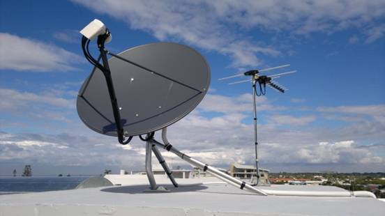
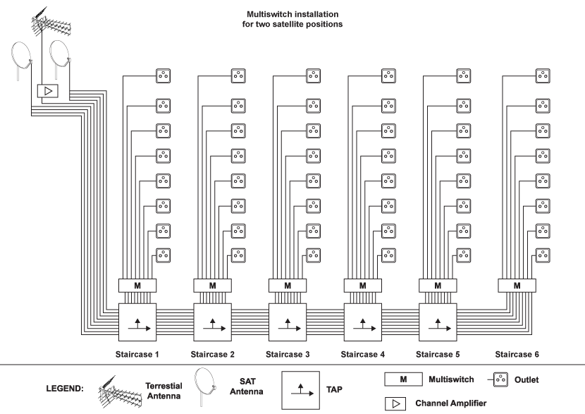
MATV systems involve a single antenna (or satellite dish) feeding multiple outlets over an entire high rise building.
Most MATV systems combine both FTA (Free to Air) and Foxtel services to each outlet.
These systems are complex in design and require a high level of knowledge skill to build.
Citywide Antenna Service can provide the expertise to: Design, Install Commission these MATV systems.
All system designs are submitted to Foxtel for approval before installation.
Once completed, the systems are tested audited by Foxtel in order to have the building “approved” for Pay TV service.
Digital Television Networks
MATV (Master Antenna Television) system is basically a television signal distribution system that sends signals from an aerial to various points. An MATV system varies in size and complexity depending on the location.
Foreign Satellite TV and Motorised Systems There are thousands of satellite TV channels to choose from, depending on your viewing requirements.
There a number of ‘Free To Air’ television channels where no monthly fee or subscription is required. There are also a number of premium subscription television channels, and also encrypted channels which require a decryption card to be unlocked. Please note, your European satellite receiver will require a CAM for these channels.
Integrated reception systems (IRS)
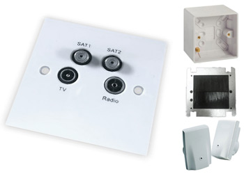
Integrated reception system (IRS) is mainly used for communal dwellings but can be applied to any property that wishes to have various reception signals routed though a single cable (or two cables for Sky + or Sky HD). The IRS system can take various signals such as, Terrestrial, Digital, FM and DAB and various satellites and combine them through the aid of a head end unit into a single cable or two cables for Sky + or Sky HD. It can be applied to anything from a single dwelling to an unlimited amount of dwellings, all receiving around the same signal level in each dwelling thus eliminating the need for numerous dishes, aerials or cabling being fitted to a communal building, so keeping the structure of the building free from clutter which can sometime deface the architectural design of a building.
If you are a builder or developer and require advice on what type of systems are available, or information on installation trends, we’ll be happy to advise. There are many new innovations which in recent months have become affordable and several which have become almost essential from a sale point of view.
• Aerials.
• Terrestrial electronics.
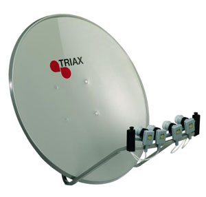
• Dishes.
• LNB’s.
• DiSEqC switches.
• Satellite’s.
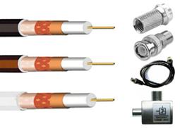
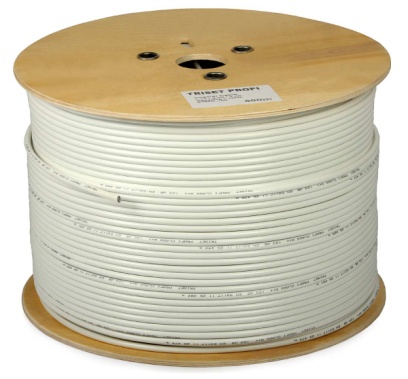
• Cable’s.
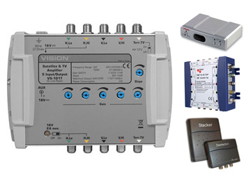
• Amplifiers.
• Taps and splitters.
• Programmable amplifier’s.
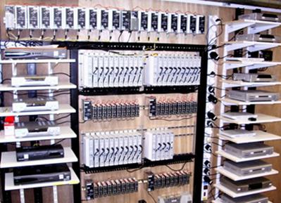
• Headend units.
• Multiswitches.
• Hybrid Fibre Coax (HFC).
• Sat-IF fibre optic products.
• Mounting accessories.
• IF amplifiers.
• IF taps/splitters.
• IF power supplies.
Reception
The cable TV headend will normally have several large C-Band FSS-type television receive-only satellite television dishes for reception of cable/satellite TV networks. A dedicated, non-movable dish is required for each satellite that the cable TV utility wishes to receive cable channels from for distribution over its system. For reception of signals from several adjacent satellites, a larger non-parabolic multi-satellite dish (such as the Simulsat) that can see up to 3 or more satellites is often used. Many digital cable systems use a unit of Comcast, which carry hundreds of channels on just a few satellites; this is commonly used by small systems to expand service without.
adding expensive new dishes or other equipment Most cable TV systems also carry local over-the-air television stations for distribution. Since each terrestrial channel represents a defined frequency, a dedicated commercial-grade receiving antenna is needed for each channel that the cable company wishes to receive and distribute. Smaller systems may use a broadband antenna to share several channels. These antenna are often built into a single tower structure called a master antenna television structure. Commercial TV pre-amplifiers strengthen the weakened terrestrial TV signals for distribution.
Some cable TV systems receive the local television stations’ programming by dedicated coaxial, microwave link or fiber-optic line, installed between the local station and the headend. A device called a modulator at the local station’s facilities feed their programming over this line to the cable TV headend, which in turn receives it with another device called a demodulator. It is then distributed through the cable TV headend to subscribers. This is usually more reliable than receiving the local stations’ broadcasts over the air with an antenna. However, off-air reception is used as a backup by the headend in case of failure. In some cases systems receive local channels by satellite.
Other sources of programming include those delivered via fiber optics, telephone wires, the Internet, microwave towers and local Public-access television channels that are sent to the cable headend on an upstream frequency over the cable system itself (known in the industry as “T”-channels), or via a dedicated line set up by the cable company, as mentioned earlier for reception of local television stations’ programming by the headend.
Signal processing
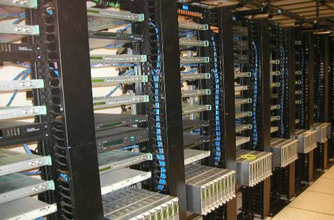
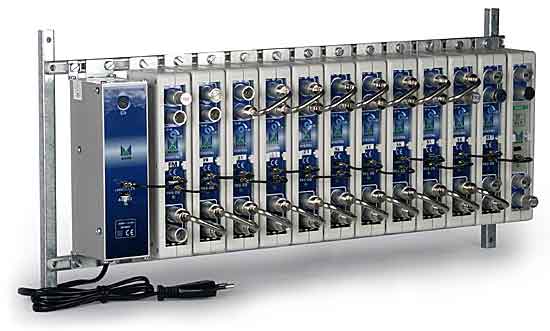
A standard rack mount headend
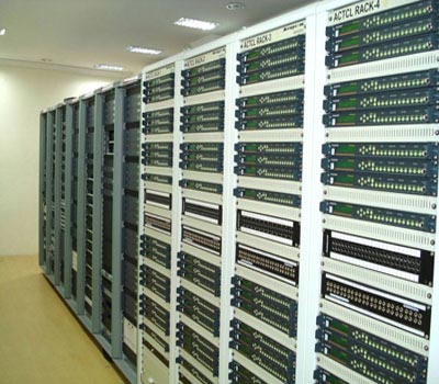
Once a television signal is received, it must be processed. For digital satellite TV signals, a dedicated commercial satellite receiver or a Scientific Atlanta/PowerVu satellite receiver is needed for each channel that is to be distributed by the cable system; these are usually rack-mountable receivers that are designed to take up less space than consumer receivers. They output video and stereo audio signals as well as a digital signal for digital plants.
Analog terrestrial TV signals require a processor which is a RF receiver that outputs video and audio. In some cases the processor will include a built-in modulator.
Digital terrestrial TV signals require a special digital processor.
Digital channels are usually received on an L band QAM stream from a satellite, which uses multiplexing. Using special receivers such as the Motorola MPS, the signal can be demultiplexed or “Demuxed” to extract specific channels from the multiplexed signal. At this point, local insertion may be performed to add content specifically targeted to the local geographic area.
Modulation
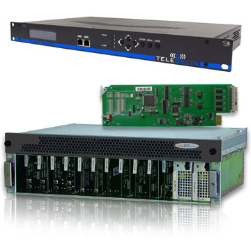
CATV Agile Channel Modulator
Cable television signals are then mixed in accordance with the cable system’s channel numbering scheme using a series of cable modulators (one for each channel), which is in turn fed into a frequency multiplexer or signal combiner. The mixed signals are sent into a broadband amplifier, then sent into the cable system by the trunk line and continuously re-amplified as needed.
Modulators essentially take an input signal and attach it to a specific frequency. For example in North America, NTSC standards dictate that CH2 is a 6 MHz wide channel with its luminance carrier at 55.25 MHz, so the modulator for channel 2 will impose the appropriate input signal on to the 55.25 MHz frequency to be received by any TV tuned to Channel 2.
OUR BRANDS